Getting Started with EFR32 Host in NCP Mode
This page describes how to get started with developing an application on EFR32 host in Network Co-Processor (NCP) mode, where the application runs on the EFR32 host and the connectivity stack runs on the Wi-Fi chipset.
Hardware Requirements
The following hardware devices are required for executing Matter over Wi-Fi for NCP Mode:
Refer, Hardware Requirements
Additional hardwares required for NCP Boards:
Windows/Linux/MacOS computer with a USB port
USB cable for connecting WSTK Board to Computer
Raspberry Pi with a >32 GB SD Card
Access Point with Internet Access
Interconnect board (included in the Wi-Fi kits)
SPI Cable (included in the RS9116 kit)
Jumper Cables (included in the RS9116 kit)
Software Requirements
Below are the software tools, packages and images required for executing Matter over Wi-Fi for NCP Mode:
Software Tools Requirements
Simplicity Commander for flashing bootloader and binary on EFR32 Boards
Tera Term for flashing firmware on EFR32 NCP Boards.
Putty for controlling EFR32 hardware using chip-tool controller
Ozone Debugger for logging and debugging (Optional)
JLink RTT for logging only (Optional) To install above software tools , refer Software Installation
Connect the Boards to a Computer
Mount the EFx32 radio board on the EFx32 WSTK board.
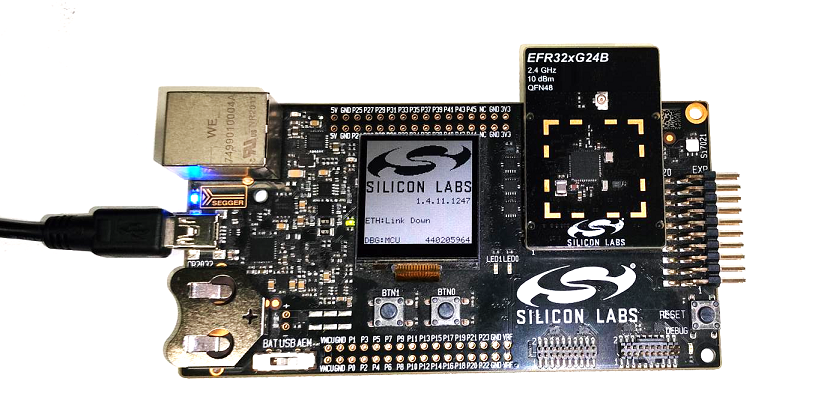
Connect the NCP expansion board to the EXP header on the EFx32 WSTK board.
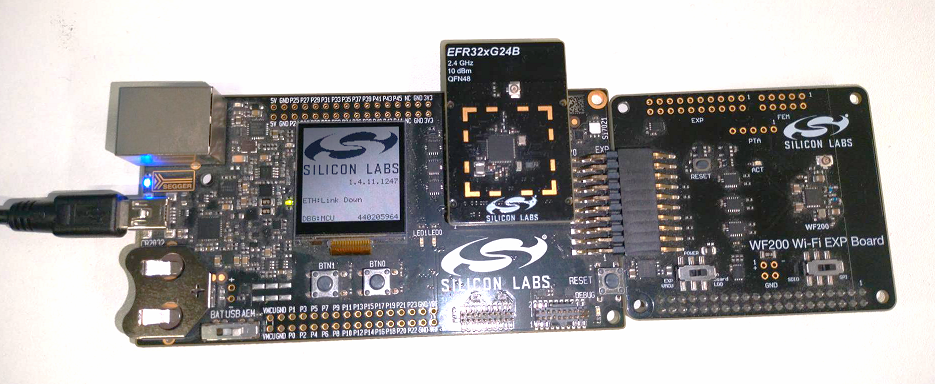
Toggle the upper switch on the NCP expansion board to EXP-UART.
Updating NCP Boards Connectivity Firmware
We recommend to upgrade the NCP combos connectivity firmware to the latest available version when
first received a EFx32 evaluation kit (EVK)
first received a radio board,
Download the recommended version of firmware before you start with the update process from the Matter Artifacts page
Steps to update the firmware on NCP boards using Tera Term
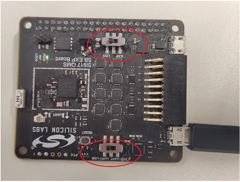
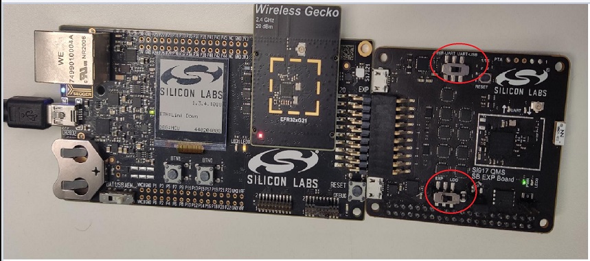
SiWx917 NCP or RS9116 EVK connectivity firmware can be upgraded using tera-term or kermit.
Make sure that the switches on the expansion board are towards UART side.
Refer Updating the Firmware
Note:Instructions are the same for both SiWx917 NCP and RS9116 EVK.
Once firmware flashing is done make sure to make switches back to Expansion mode, while using it with the host platform.
Troubleshoot NCP Firmware Update Failure
If the firmware update fails, try the following:
Toggle the power switch towards AEM (Advanced Energy Monitoring) on the WSTK board.
Perform the following steps and try the firmware update again
Toggle the ISP switch towards ISP on the radio board.
Press the RESET button on the WSTK board.
Toggle the ISP switch away from ISP on the radio board.
In the Flash section in step 5 above, click Erase chip.
The flash will be erased.
Retry the firmware upgrade.
Building Matter Application on EFR32 device
To build Matter Application on EFR32 device, refer Building Procedure
Flashing Images/Binaries on EFR32 Platform using Ozone, or Simplicity Commander
Plug the WSTK and EFR into the laptop.
Based on the Application being built, make sure to flash proper bootloader internal or external binaries.
Launch Ozone, or Simplicity Commander Standalone - this will display a GUI.
If you are using Simplicity Commander, you can follow the general instructions for flashing a Silicon Labs device. Flash a Silicon Labs Device. If you are using Ozone, you can follow the instructions below.
Directions for Flashing using Ozone
In ‘New Project Wizard’:
Click the three-dots on the ‘Device’ tab and select ‘Manufacturer’ as ‘
Silicon Labs’Select ‘Device’ as
EFR32MG24Bxxx1536depending on the device you are using.Click ‘OK’
The ‘Register set’ tab will get filled automatically
‘Peripherals’ tab need not be changed as it is optional
Click ‘Next’ - the window that is displayed will contain:
Serial Number: Read from device
Target Interface: JTAG
Speed: 4MHz
Host Interface: USB
There will be one product in the ‘Emulators connected via USB’ tab - select this and click ‘Next’
Click on the ‘Silicon Labs device’ detected, and then click ‘Next’
You will be asked to select the image/binary to be loaded: click the three-dots on that tab and navigate to ‘
out/rs911x_lighting/BRD41xxx’ through ‘Browse’, select the file namedchip-efr32-lighting-example.outand click ‘Next’. This is the image built in previous step.Note that you may be using a different board like the BRD4186C or BRD4187C, in which case your image will be in a directory corresponding to that board identifier.
Make sure the next screen has ‘Initial PC’ selected as ‘ELF Entry Point’ - click ‘Finish’
Ignore Diagnostics warning about ‘FreeRTOS’ detected - click ‘Continue’
Select ‘Download and Reset Program’ in the dropdown next to the Power button on the top left of the page
The Silabs chip, EFR32MG24, will be erased and programmed
Run the image by clicking the ‘Play’ button on the top left (or press the F5 key)
The output of the EFR32 can be viewed on the console of the Ozone GUI
[Optional] This step is for when the device has already been flashed and is being used for testing/debug purposes:
If you are restarting the device and do not need to re-flash the EFR firmware, then you can use these commands (JLinkExe & JLinRTTClient). The following commands will provide you with a serial console of the EFR32
$ console -e JLinkExe -device EFR32MG24Bxxx1536 -if JTAG -speed 4000 -autoconnect 1 &
(Put it in the background)
$ sleep 3
$ console -e JLinkRTTClient &
You may need to press
in the JLinkExe console first
Enabling JLink RTT Logs for EFR32 Boards
Open JLink RTT Viewer and click on three dots beside Specify Target Device
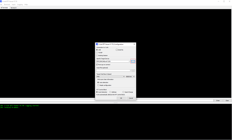
select Manufacturer as Silicon Labs and device section search
EFR32MG24BxxxF1536orEFR32MG12PxxxF1024as per board connected to machine then click “ok”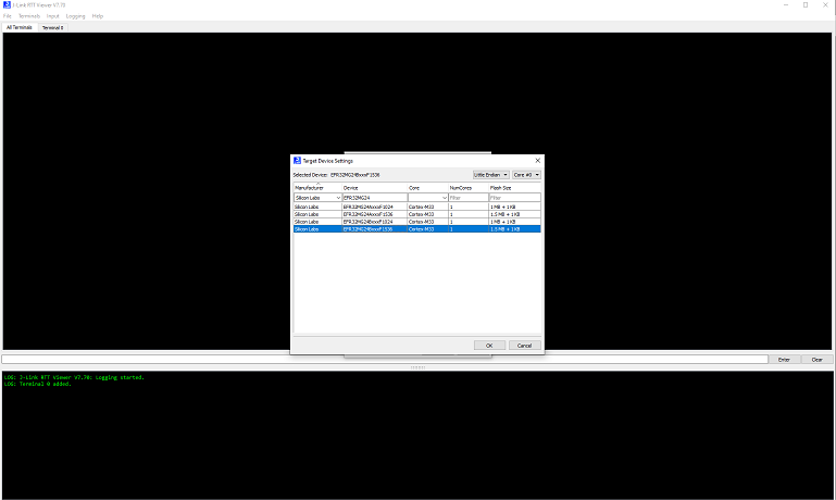
Select Target Interface as
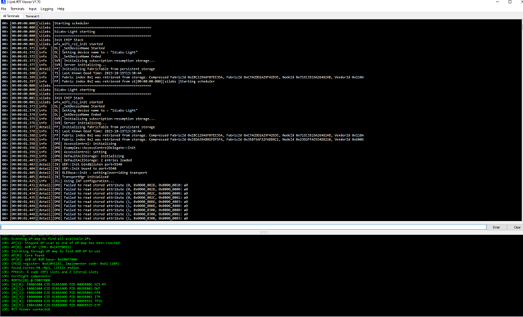
JTAG& Speed as8000KHz(Default) then click “ok”Now the JLink-RTT is connected and will print the device logs
Demo Execution - Commissioning a Wi-Fi Device using chip-tool for Linux
Commissioning can be done using chip-tool running either on Linux or Raspberry Pi
Get the SSID and PSK of the Wi-Fi network (WPA2 - Security) you are connected to.
Run the following:
$ cd $MATTER_WORKDIR/matter
Commissioning Command:
$ out/standalone/chip-tool pairing ble-wifi 1122 $SSID $PSK 20202021 3840
The node ID used here is 1122. This will be used in future commands. ‘$SSID’ is a placeholder for your Wi-Fi SSID and ‘$PSK’ is a placeholder for the password of your Wi-Fi network.
To turn on the LED on the EFR32MG24:
$ out/standalone/chip-tool onoff on 1122 1
To turn off the LED on the EFR32MG24:
$ out/standalone/chip-tool onoff off 1122 1
If there are any failures, run the following command and then re-run the chip-tool command:
$ rm -rf /tmp/chip_*
If you are having difficulty getting the chip-tool to commission the device successfully, it may be because you have more than one network interface available to the chip-tool. The device on which you are running the chip-tool must be on the same Wi-Fi network as your RS9116 or WF200 and there cannot be another network interface on the device that is running the chip-tool. For instance, if you have an Ethernet connection as well as a Wi-Fi connection, you need to unplug the Ethernet connection and try running the chip-tool as in step #2 above.
As the device remembers the Access Point credentials given for commissioning, if you want to run the demo multiple times, do a factory reset by pressing the BTN0 on EFR32MG24 for about 6-7 seconds. The LED0 will flash 3 times.
The commissioning command mentioned above does the following:
chip-tool scans BLE and locates the Silicon Labs device that uses the specified discriminator
Sends the Wi-Fi SSID and Passkey
The Silicon Labs device will join the Wi-Fi network and get an IP address. It then starts providing mDNS records on IPv4 and IPv6
chip-tool then locates the device over Wi-Fi and establishes operational certificates
Future communications (tests) will then happen over Wi-Fi