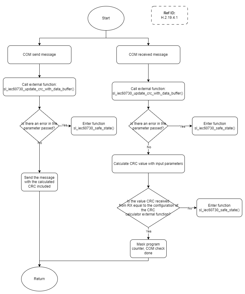
Verifies communication channel is operating as expected. More...
Verifies communication channel is operating as expected.
Hardware Architecture
For communications interfaces to be IEC60730 compliant, they must meet the following conditions:
- Provide address redundancy, transmitting the sender's unique address
- CRC coverage of transmission bytes
- Scheduled transmission
Each type of hardware-implemented serial interface supported by a device must meet the three above communications requirements using a combination of hardware features and firmware-implemented support.
For I2C interfaces, the protocol requires that a transaction begin with a slave address identifying the intended recipient of the message, which meets requirement 1. Each message transferred must end with a 2-byte CRC covering all transmitted bytes. Hardware CRC generation is available on some devices and a buffer of bytes can generate a CRC using the sl_iec60730_update_crc_with_data_buffer provided, which meets requirement #2. Requirement #3 can be met by initiating a periodic transaction using the test timer allocated for the system clock plausibility check.
A SPI interface meets the requirements above in a way that is similar to the I2C interface, except that an address must be included through firmware, because the protocol and the hardware do not support a slave address inherently.
A UART interface meets requirements similar to a SPI interface, where the address must be transmitted through firmware implemented protocol.
Failure Risks
A disruption of the serial interface signals/clocks could cause a bit of error or a timing-related issue. This will result in a CRC mismatch when the receiver of the message processes the packet and safe state entrance.
If the device sending status packets to a host gets somehow stuck in such a state where it is unable to transmit status packets, the receiver expecting periodic packets will enter a safe state after a bounded amount of time, likely governed by a bist frequency check that determines no status packets have been received within a frequency check interval. Based on the suggested configuration of the bist frequency check period, the upper limit for the time between the reception of a status packet would be 1 second. Based on the suggested configuration of the test timer, typically the status packet will be transmitted once every 100 ms.
All serial interfaces require some amount of port configuration to ensure that the correct pins are digital inputs and outputs, open drain, or push-pull. Without these requirements being met, the device will be unable to transmit and receive data packets properly, which will result in a safe state entrance by one or both of the devices communicating across a serial interface.
Software Architecture
The library provides a support function sl_iec60730_update_crc_with_data_buffer() to generate the CRC of a buffer being transmitted. OEM firmware is responsible for interfacing with serial communication hardware to send packets that begin with address information to identify the sender and end with a 2-byte CRC.
In order to transmit a status packet, the device needs to allocate an on-chip timer, or use the test timer already allocated for the system clock plausibility check.
Devices receiving status packets rely on a bist frequency check where one requirement for the comm plausibility test to have executed successfully is the reception of a valid status packet.
Figure 1 shows the main components of both a receiver and a transmitter of a compliant serial interface. Note that received packages are processed by checking for an address and a valid CRC. Additionally, a bist frequency check determines whether status packets are being received at an acceptable rate. For transmission, all data payloads go through firmware that adds required address and CRC information. Additionally, the test timer interrupt service routine initiates a periodic transmission of a status packet.

 1.8.17